
Articles
Connel Bridge:
Celebrating 120 Years
By David Pritchard CEng MICE

Connel Bridge is a remote road crossing within the Scottish Highlands situated five miles northeast of Oban. It spans the mouth of Loch Etive at a narrow and picturesque juncture where a natural tidal race is formed caused by rapid ebb tide flows from the Inner Firth of Lorne. The bridge forms a critical link within the trunk road network in this remote region, with the alternative route for reaching the opposing estuary bank involving a 90-mile round road trip via Bridge of Orchy and Glencoe. When completed in 1903 Connel bridge was the second longest cantilever and suspended span bridge in Europe, surpassed only by the Forth Rail Bridge, built in 1890.
Connel Bridge has been re-purposed throughout the last 120 years. Up to 1914 the bridge solely carried railway traffic and a footway. To meet the demands of locals seeking an alternative to the existing ferry crossing, after 1909 a passenger service comprising cars carried on flatbed wagons hauled by a rail-mounted charabanc operated between Connel Ferry and Benderloch stations.
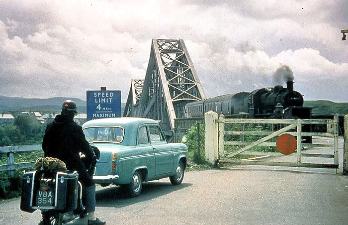
In 1914 the bridge was converted to also accommodate one lane of road vehicles alongside the existing single-track railway. Following the closure of the railway in 1966 the bridge was converted again, this time to accommodate a wider single lane for road traffic vehicles and a narrow footway for pedestrian traffic; the configuration which has endured to the present day.
Today the Category B listed bridge carries approximately 5,200 vehicles every day and carries the A828 trunk road across the estuary to a nearby T-junction with the A85 trunk road situated on the southern bank.
Key Data

Location
A828
Connel,
Argyll and Bute

Designer
Sir John Wolfe-Barry & Partners
(Brunel & Cruttwell),
Formans & McCall

Contractor
Arrol Bridge & Roofing Company, Glasgow

Construction
September
1898 to
August 1903

Cost
£400,000
(Total cost of railway project)
Planning and Design
Prior to Connel Bridge’s existence, the estuary crossing was operated by two ferries which operated between Connel and North Connel. This has been traced as far back as the 1600s and it is for this reason that the village on the southern bank is known as Connel Ferry. Based on photographs, the ferry appears to have been a rowing boat. Traveller accounts dating as far back as 1797 describe the ferry as transporting both people and horses - it seems horses were either transported on the boats or towed alongside them.
Connel Bridge was originally built between 1898 and 1903 by the Caledonian Railway Company as part of the Ballachulish branch line from the Callander and Oban Railway. The line’s original purpose was for transportation of slate from Ballachulish quarries and to deliver bauxite to the Kinlochleven Aluminium Works. The route was built towards the very end of the UK railway network’s significant expansion period which occurred throughout the Victorian era. The line was originally intended by the company to reach as far as Fort William however, in the end it only reached as far as Ballachulish.
Initially Connel Bridge carried a single railway track and contained surplus width which could satisfy future growth in demand. As trains could run in either direction on the same track, conventional scarfed joints for accommodating expansion and contraction movements between suspended spans and cantilever spans could not be opted for. The pointed scarfs could be prone to projecting slightly inwards, creating an impact obstruction to oncoming wheels in one of the directions travelled. Consequently, designers developed an alternative detail called a ‘butt’ or ‘joint piece’ rail. This detail comprised of the rails, thinned in their width, sliding longitudinally guided between cast iron joint rails and clips flanking either side. Within the length of the flanked sections a nominal 76mm clear gap could be formed between the thinned rails, thus permitting the desired movement.
The bridge was built to monopolise access to the area of North Lorn for the Caledonian Railway Company’s interests, rather than those of the local communities. Consequently, its construction marked a period where the local authorities, keen for an improved alternative crossing to the primitive ferries, sought for the bridge to become a dual-purpose structure to better serve the interests of the local population. Whilst successful, fully obtaining their objective took more than a decade; with the railway company appearing somewhat slow and evasive on the matter before eventually yielding.
The railway company’s first attempt to satisfy the needs of the locals was provision of a bus-like vehicle (known as a charabanc) mounted on railway wheels which transported pedestrians across the bridge. A railway wagon was also hauled by the charabanc to carry road cars across the bridge. This system quickly became unsustainable, particularly with car-ownership in the UK on the rise around the 1910s bringing with it increased road traffic volumes.

A bus-like vehicle known as a charabanc was introduced to the bridge in its early years to transport locals across the bridge. The vehicle was also capable of hauling cars in a railway wagon.
It wasn’t until 1913 that a local named James MacAlpine made a political move which made the railway company relent and make the bridge dual-purpose for road and rail. He achieved this by applying to the board of trade to operate a rivalling chain ferry link across the estuary close to the existing Connel Bridge. Whether MacAlpine was truly enterprising for the chain ferry, or simply pitching the proposal as a front to spur the railway company on to make the bridge dual purpose is not known. Thus marked the conversion of the bridge into a dual-purpose structure servicing both road and rail vehicles completed on 22nd June 1914; approximately five weeks before the outbreak of the First World War.
Due to the constraint of its narrow deck width, the bridge was unable to accommodate passage of road and railway traffic simultaneously with safe segregation between them. For this reason, gates closed the bridge to road traffic at either end when trains were passing, forming an arrangement synonymous with a conventional level crossing. Tolls were applied for the road traffic and timber barriers prevented errant vehicles from straying onto the railway tracks whilst crossing. Initially the bridge was closed to road vehicle traffic overnight (exceptions made for emergency vehicles) prior to eventually being opened 24/7 with the tolls manned in three shifts.
Following the demise of the railway in 1966, as part of Beeching’s ‘The Reshaping of British Railways’ commonly referred to as the ‘Beeching Axe’, the bridge was repurposed again. The line was lifted, and the decking modified to cater to a 3.6m wide single lane for road traffic, a rather narrow 1.3m wide footway for pedestrians to one side and a 0.6m wide hardstanding to the other. Traffic lights at either end ensure one-way traffic flows and this configuration has remained largely unaltered to the present day.
Designs for this re-purposing of the decking in the late 1960s were prepared by Fairhurst, and the contracting company Sir William Arrol was also involved (not to be confused with Arrol Bridge and Roofing company who originally built the bridge). In section, the decking panels comprise of six longitudinal steel beams, called stringers, which rest directly upon the cross girders of the main bridge truss later described. These stringers are interconnected to reinforced concrete slabs above them which span transversally, with the latter directly supporting the vehicle carriageway. The deck panel structural configuration is termed as ‘steel-concrete composite’. The decking panels are segmented, with each spanning between any two given cross girders. As such, they effectively form a series of shorter bridges within the overall bridge, with the span of any given segment being no greater than 4.9m in length. This decking has endured since its implementation, but it is scheduled for replacement in the near future due to deterioration.

Superstructure
The central portion of the bridge is constructed from mild steel riveted plate girders. From the early 1800s, cast and wrought iron were conventional building materials for bridges and may have been selected for Connel had the bridge been constructed at an earlier time within the railway expansion period. However, by the time of Connel Bridge’s late arrival into the 20th century, steel had fully emerged as dominant. Wrought iron began to be supplanted by steel around 1850, and beyond 1890 its production for building purposes was minimal. By contrast for steel, in the 1880s its availability in larger sections sizes and quantity increased considerably. Reasons that brought about the change of material preference were both technical and commercial:
-
Cast and wrought iron containing greater quantities of impurities which can lead to brittle failures at lower stresses. By contrast, steel contains fewer impurities and its mode of failure is ductile rather than brittle, hence less likely to lead to a collapse.
-
The manufacture of steel became more cost-effective by comparison to wrought iron as of the 1880s.
It is notable that two important railway bridges in Scotland played significant roles in marking this general industry transition from wrought and cast iron to steel:
-
The Tay Railway Bridge collapse in 1879. A bridge built of cast and wrought iron.
-
The precedent offered by the Forth Railway Bridge. A cantilever bridge successfully built of steel, in part from lessons learned following the Tay Bridge disaster.
To give context to what might have been in the designer’s mind at the time of designing Connel in regard to material specification, a quote from ‘Forth Bridge’ by W Westhofen from 1890 considers the usage of steel as the material for the Forth Bridge, published approximately eight years prior to Connel’s construction:
”From the beginning - and probably a long time before the beginning of this work- to the end, this steel was subjected to every conceivable test, both in a properly scientific manner for purposes of research or investigation, and in an entirely unscientific manner by workmen, whose only excuse can be that they did not know better. But in all cases the steel stood the test, and a more uniform, a more homogenous, and mere satisfactory material could not be wished for” [1]

Elevation View
The overall structural form of the bridge can broadly be divided into five sections. Two of these, the north and south approaches, are conventional masonry arch bridges, each comprising of three spans. Record design drawings demonstrate the southern approach was originally envisaged to have four spans. This was later reduced to three for reasons not known. Adjoining each of the approaches are steel cantilever trusses. The trusses reach outward over estuary from the banks, with their extremities forming bearings that support either end of a single suspended truss that spans across the middle of the estuary. The suspended truss can be easily discerned from its adjoining cantilevers due to it having flat top chords, whereas the top chords of the cantilever trusses are sloped and reach apexes set 36.0m high from the piers. Interestingly, each apex is inset 16.4m inward towards the estuary from its supporting pier. The designers purposely orientated this to shorten the lengths of the overhanging portions of the cantilever trusses beyond the main legs. In this arrangement, the pier foundations were offset outward from fast tidal flows and could be built in shallower water accessible via cofferdams. Cantilever bridges then have the advantage of being able to be constructed outwards from their point of support without direct vertical support from beneath, and in this way the fast-flowing water could be avoided.

From a simplistic perspective, the structural behaviour of one of the cantilever trusses can be compared to that of a seesaw in a children's playpark. Viewed wholistically as a seesaw, each cantilever truss is effectively a long beam with a centred hinged support which is built on a solid foundation. Adopting this analogy, one end of the seesaw (the overhanging end of the cantilever truss reaching out into the estuary) is heavily loaded by the suspended part of the bridge which spans the middle of the estuary. For the seesaw to successfully carry all this concentrated weight at one end, it requires counter balancing at the other to prevent it simply tilting inwards toward the estuary. This involved tying the opposing end of the cantilever trusses down to counterweights positioned within end piers adjoining the approach spans. Each counterweight is made up of two discrete steel anchor ties (each comprising two steel channels) reaching down to a transversely orientated steel anchor girder weighted deep in the pier by approximately 2500 imperial tons of granite masonry above. This was weighted by the designers to counter approximately twice the maximum tension that could be experienced in the ties.

Cross Sectional View at Pier

As to the hinged supports over piers, an earlier version of the detail shows the designers aspiring to form a literal hinge which can clearly be observed incorporated into the steelwork connection. This comprised a 2.0m diameter curve at the bottom of the main leg able to rotate within a base socket suitably formed to the same diameter, and a sliding interface created between the two. Later revisions of the same drawing show this hinge removed. The reasoning for this significant design alteration is not known, but could likely be one of the following:
-
Fabricators highlighting concerns (excessive expense/buildability issues or otherwise) to the designers as to difficulties involved in forming such as large complex hinge to required tolerances.
-
Designers, through refinement, deciding the detail could be simplified with articulating hinge detail able to be removed. This would perhaps be due to calculated rotations encountered at this interface being sufficiently minor, demonstrating a simpler base plate detail (without a physically formed hinge) could suffice without causing distress to the structure nor the pier beneath.

At this interface between the piers and cantilever truss skewbacks we come across one particularly good illustration of the bridge’s exemplary steelwork detailing. Here the designers had to contend with interfacing large plated structural steelwork members of varied size and built-up section approaching each other from four different directions, all converging on to an inclined bottom plate and all needing to interconnect with each other to ensure the correct distribution of stress. The complexities designers overcame with the jointing by hand on structures around this period is so impressive that it could arguably be considered an almost lost artform in engineering. Particularly so, considering this bridge was designed at a time long before the invention of the calculator and computer aided design.
The overriding structural principles applied in the design of Connel were virtually the same as those used to design the more widely renowned Forth Railway Bridge. Incidentally, the famous image below, which was used by the Forth Railway Bridge engineers to demonstrate the cantilever principle the Forth Bridge, is a close representation of the overall Connel bridge arrangement: two cantilever trusses (represented by people in chairs), a single suspended span, and two counterweights.

This famous photo, taken by engineers involved in the design of the Forth Rail Bridge, clearly demonstrates the principles behind cantilever bridges such as Connel.
Despite the obvious similarities, there are subtle, but fundamentally significant, differences between the designs. The form of trusses at the Forth Railway Bridge are predominantly known as double-warren girders (this form of truss creates those rather conspicuous X's along the full length of the bridge), and trusses of this kind are commonplace. By comparison, the form of truss used at Connel bridge, called a Baltimore Truss, is much less common in the UK and as its name suggests, was almost exclusively an American type. A Baltimore truss is a variant of a Pratt Truss a.k.a. N-Girder. It contains additional members called sub-verticals which act as suspender ties. These offer additional intermediate support at the centre of each bay for supporting bridge decking by comparison to an N-Girder. The additional tie forces generated by the sub-verticals need counteracting, and this is provided by the additional diagonally orientated raking struts reaching from the top of the sub-vertical to the bottom corner of the bay.

Annotated Diagrams
The connection between the cantilever and suspended spans forms a half-joint configuration which is extruded vertically as a strut has been introduced able to articulate between the upper and lower nibs. Through this, the strut can translate slightly about points of rotation, allowing the bridge to accommodate small longitudinal movements.
This allows the bridge to expand and contract with temperature without generating adverse concentrations of stress within the structure. Interestingly, between these joints the bridge is also centred. This is through provision of ‘volute springs’ at each of the half joints which apply a small amount of equal and opposite tension at each end of the suspended truss to keep it centred, with the expansion gaps at either end equal in width.

Substructure and Foundations
The bridge foundations are founded directly upon rock. The piers themselves contain some of the bridge’s most impressive engineering features completely obscured from view.
Firstly, there is the hidden ashlar bedstone cited directly beneath the hinged bedplates for cantilever trusses. Design drawings reveal the coursing of the bedstones steadily fans out away from the horizontal plane steadily over four courses. This ensures the top stone course meets the hinged bedplate orientated perpendicular to the direction of force coming down from the member which bears the compression arising from the cantilever truss. Here the designers clearly implemented this to mitigate the tendency for ashlar courses to slide over each other in the horizontal direction (a shear plane failure) when subjected to the component of transverse thrust from the superstructure. The bedstones are large, reaching 2.3m in length. The load bearing fanned coursing would have added complication to the stonework geometry and likely demanded the highest quality of stonemason workmanship available at the time. To have built the entirety of the piers in such high-quality ashlar would have been very expensive, so the designers confined the high quality ashlar to where it would be most structurally effective, with the remainder predominantly composed of squared blocked rubble stone.
Notably, the two piers that support hinges of the cantilever trusses contain post-tensioning in the transverse direction. When we speak of post-tensioning this is usually applicable to its application in reinforced concrete beams commonly built approaching the middle of the 20th century. However, in Connel Bridge many decades prior, we find it as a measure to facilitate counteracting the horizontal force component imposed by the transversely splayed legs of the cantilever truss. The records demonstrate configurations of hydraulic jacks and distributing girders used to tension arrangements of four steel tie plates against the ashlar stone. 100mm-wide chases were created within the stonework to allow grouting following the tensioning, again an early form of what would go on to become the more atypical post-tensioned duct found in reinforced concrete bridges. One of the drawings also notes “an initial tension of six tons per sq. inch will be put on the ties in accordance with the Engineers directions”. [5]

Construction
Construction of the abutments and piers began in 1898 and in May 1900, manufacture of the bridge’s structural steelwork commenced at the Germistone Works of Arrols Bridge and Roof Co, comprising 2600 imperial tons of steelwork. Large sections of the steelworks were prefabricated at Glasgow facilities prior to being transported to site. An indicator of the extent of girder pre-fabrication vs in situ construction is the estimate that overall, approximately one third of the total riveting was carried out at the bridge site. The remainder was pre-riveted in the fabrication workshop using pneumatic compression riveters and hydraulic riveters. Approximately 200 personnel were employed in the bridge’s construction and one of the most challenging aspects was noted as finding suitable temporary accommodation for the large workforce based at the remote site.
Firstly, bottom main girders known as back struts were erected spanning between the in-land pier and estuary pier. From these, the main cantilever triangle was erected with main girders (main legs and back ties) extruding upwards from ends of the back strut. Construction photos show that erection of the approach masonry arches followed on after the erection of the steelwork cantilevers was well underway.
Prefabricated girders were transported from the Garmiston yard to the Connel site by rail. The southern estuary bank had a railway connection for delivery of the materials. Reaching the north bank of the estuary necessitated an additional leg of the journey via steamer across to Kentallen near Ballachullish, and from there materials being carried southward by rail to North Connel.
The apportioning of the suspended span being lengthy, and therefore heavy, in comparison to its adjacent cantilevers presented a significant construction challenge. A conventional ideal for a suspended span within a bridge is that it can be sufficiently light in weight and small so that it can be economically pre-erected and simply lifted and lowered into place. However, for a suspended span of such magnitude as Connel this would have been uneconomical to achieve and would have necessitated cranes of unfathomable magnitude. Moreover, alternative methods such as erecting staging to construct the suspended span from the ground up, or floating out the large suspended portion and jacking, were also impractical due to the tidal flows estuary narrows. Floating out suspended spans was successfully achieved at Robert Stephenson’s Britannia Bridge and Isambard Kingdom Brunel’s Royal Albert Bridge at Saltash. Regarding the latter, one of the John Wolfe Barry partners involved in the design at Connel was Henry Marc Brunel (the son of Isambard). One of the record drawings demonstrates this with an annotation directed toward the back struts stating that “calculated deflection of Back Strut due to weight of Back Strut and Bracing 0 5/8” camber ordered by Mr Brunel on 30 Jany 1900 to be 1” [5].

The method adopted to erect the suspended span was brilliant in its simplicity. The engineers simply designed temporary screw fixings of 200mm diameter (designed to be easily removed on completion) that permitted the suspended span to be constructed as further projections from the main cantilevers already constructed even further over the estuary.

Connel Bridge nears completion in this photo taken before completion of the suspended span. Crawler cranes used for erecting steelwork can be seen on both sides of the river.
Two cranes (one operated by hand and the other steam powered) connected to 24m long trollies resting on the bridge deck rolled to projecting 12m beyond the constructed extent to enable construction of successive bays of the overhang cantilevers and suspended span. The trolly also contained netting attached beneath as a health and safety measure to catch workers in the event of accidental falls, a measure implemented long prior to the introduction of legislation such as the Health and Safety at Work Act 1974. By March 1903 the south end of the bridge was largely completed with progress at the north end trailing by only a couple of weeks.
On 9th May 1903 the central splicing together of the suspended span occurred above the watercourse with the rivet holes meeting within 7mm of each other. Once fully connected, the temporary screw fixings were able to be released, thereafter allowing the bridge to articulate as intended.
Opening
The bridge was subjected to a load testing regime prior to opening to traffic on behalf of the certifying Board of Trade. Nine locomotives hauled four 30-ton railway wagons over the structure several times with the train speeds incrementally increased on each run. Following this, the bridge was ceremonially opened on 21st August 1903. Initial traffic volumes were five trains per day crossing the bridge each way after opening.

The Bridge Today
Today the bridge is managed by Transport Scotland on behalf of the Scottish Ministers.
One of the biggest ongoing maintenance issues with the bridge has been deterioration to its reinforced concrete decking situated beneath the carriageway. This has arisen from factors including de-icing salts penetrating down through the numerous joints in the decking leading to defects attributable to steel reinforcement corrosion from the chloride ingress. As a result, the current decking is now in poor condition to the point it needs replacing.
Since 2021, various preparatory schemes have been underway as advanced works for a replacement to the bridge’s deteriorated reinforced concrete decking. These advanced works have included:
-
Installation of temporary access system
-
Strengthening to the main structure
-
Painting
-
Utility/service diversions
-
Installation of a temporary walkway to enable pedestrians to use the bridge whilst the decking replacement is ongoing.
The replacement decking comprises segmented orthotropic steel trough stiffened units, and the works are expected to commence in 2024.
.jpg)

Further Reading
In 2020 retired engineer Mike Rayworth produced a booklet chronicling the fascinating history behind the bridge. Copies of this wonderful publication can be ordered HERE or in person at Connel Store, Appin Co-Op, and Robins Nest Taynuilt.
This article was first published in August 2023. With special thanks to Mike Rayworth.
Related Content
Podcast
A special podcast celebrating the 120th anniversary of the bridge was released in August 2023. It can be heard below.
Article References:
[1] Westhofen W (1890) The Forth Bridge, Reprinted from “ENGINEERING,”, 3rd edn. Offices of “ENGINEERING,” 35 & 36, Bedford Street, London, UK.
[2] Rayworth M (2020) Connel Bridge - A brief story of the planning, the design and its construction, 1st edn. Mike Rayworth and Print Mhor Ltd, Oban, UK.
[3] Drawings relating to Sir John Wolfe Barry's projects, C. & O. RY Connel Ferry Bridge. Details of Bed Plates at J, Contract No. 1 Working Drawing No. 44, Institution of Civil Engineers (ICE), London, UK.
[4] Drawings relating to Sir John Wolfe Barry's projects, C. & O. RY Connel Ferry Bridge - Details of Joint J, Contract No. 1 Working Drawing No. 44, Transport Scotland, Glasgow, UK
[5] Drawings relating to Sir John Wolfe Barry's projects, C. & O. RY Connel Ferry Bridge – Cantilever Span, Contract No. 1 Working Drawing No. 30, Transport Scotland, Glasgow, UK
[6] The Engineer (1903) Construction of the Connel Ferry Bridge, Reprinted from “THE ENGINEER”, The Engineer Magazine, London, UK
[7] Engineering (1903) Cantilever Bridge at Connel Ferry Reprinted from “ENGINEERING,”. Offices of “ENGINEERING,” 35 & 36, Bedford Street, London, UK.